Wednesday 29 May 2013

Calculating State of Charge from Terminal Voltage

So now I have some data, I need to calculate the state of charge from the terminal voltage. My plan is to watch the current and voltage readings over time and try and take a voltage reading once the battery has been 'at rest' for a period of time. In reality the battery is always in use in some way, as seen by the graph in the previous post. However overnight there is no charging as the solar panel produces no output. The fridge cycles on and off, but I hope to be able to take the highest voltage reading before the voltage drop in the cycle happens.

Once I get that voltage reading I need to convert it into an estimation of the state of charge of the battery. I managed to find a good table that lists state of charge versus voltage and that is temperature compensated. I have a temperature probe on the battery terminal to measure the temperature. As I use the van all-year-round and live in the UK and sometimes go to France, this means the battery temperature could vary from 0 to 30 degrees C.

The table I found is on Battery FAQ and has a spreadsheet that lists no only voltages for normal lead acid batteries, but also those with calcium in. The penny has now dropped that my Lucas LX31MF batteries are calcium batteries. This explains why they settle at 12.80V instead of 12.65V. Also why they seem to need a higher charging voltage. I think for the past few years I have been charging them at too low a voltage and hence their poor performance.

I took the tables in the spreadsheet and ran them through some curve-fitting software to work out an equation that best fits the values. This makes is much easier for me to calculate the temperature compensated voltage and the SoC. The equations I came up with in the end for a calcium battery are:

# Given voltage and temperature return a corrected voltage
def tempcomp(v, t):
    return v + (4.775e-05 * t ** 2 + -0.0034 * t + 0.0581)


# Given voltage return an estimate of the state of charge of battery
def vtosoc(v):
    return (v - 11.76) / 0.0104

Of course these are approximations  Even worse they are approximations taken from random data on the internet, and not from data specific to my battery. But then, my battery manufacturer  Lucas, doesn't publish battery data. Given that most battery monitors out there don't allow you to input any parameters other than just the battery bank capacity, I think I'm doing at least as good as they are.

Tuesday 28 May 2013

Data!

So, I finally have some actual real, useful data captured!

This last weekend was a bank holiday weekend in the UK and so we went camping down in Weymouth by the sea. We drove down Friday evening and left Monday afternoon. So we were there for three nights. There was no electrical hookup, so we would be relying on the batteries alone. We've stayed that length of time before just on batteries, but I've never been able to instrument how the batteries were doing and was never very sure of how well they were working. My gut feeling was always that we were running dangerously low at the end.

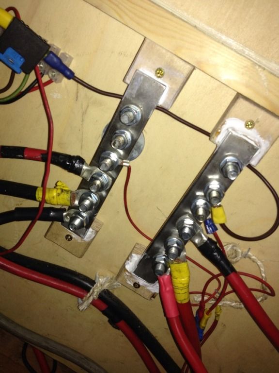
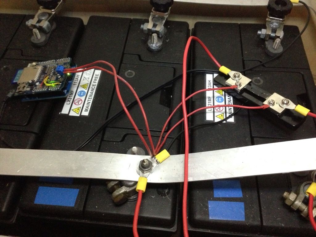
Since then I have re-done the main battery cabling and built some new bus bars, and so I think the connections are much better. I've also got a much better ground connection as well, using a M8 rivnut into the van floor rather than just a 3mm pop rivet. I've also dropped one battery. I originally had 3 x 115Ah batteries, but I feared one (at least) was dead and removed it. So I'm now just running on 2 x 115Ah batteries.

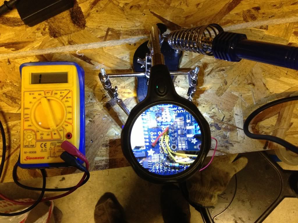
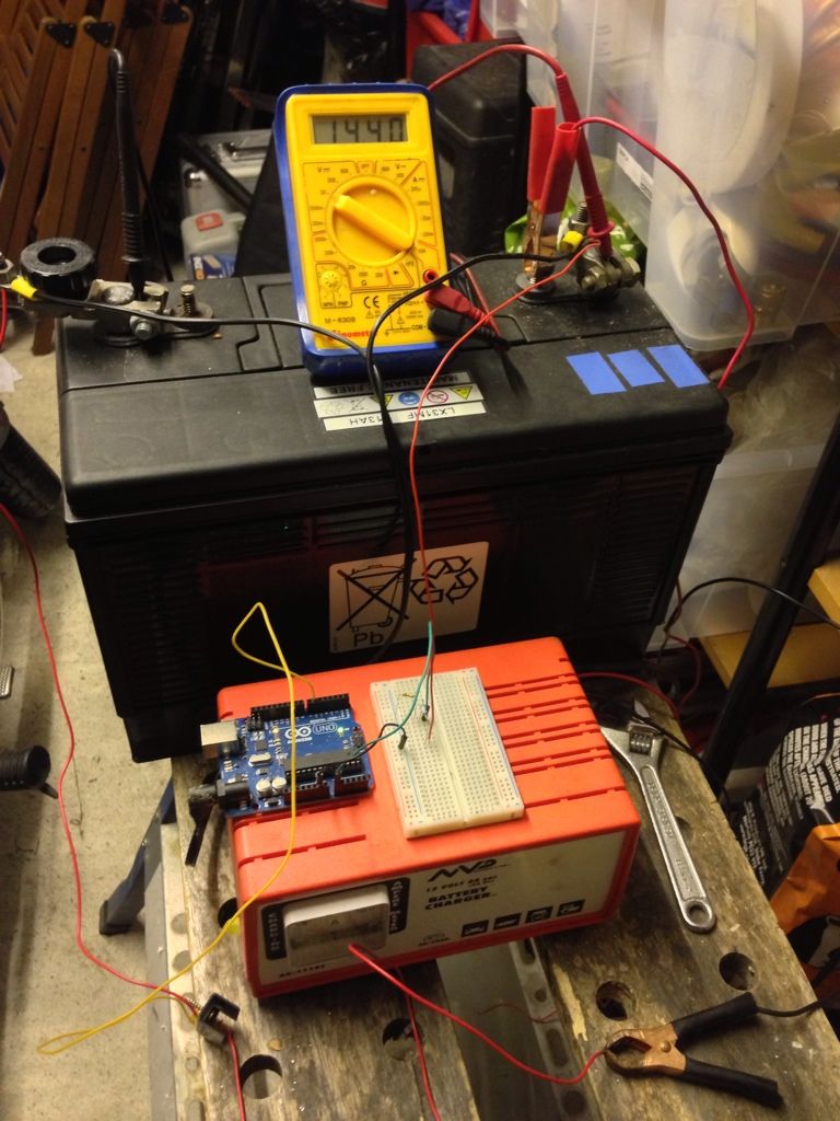
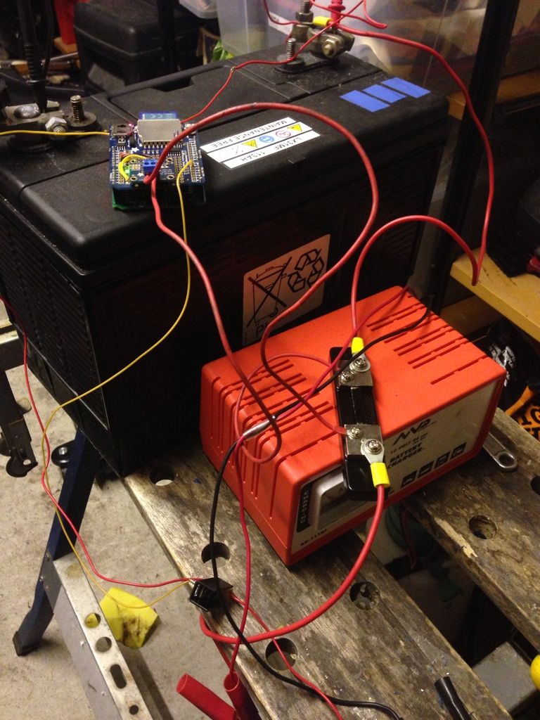
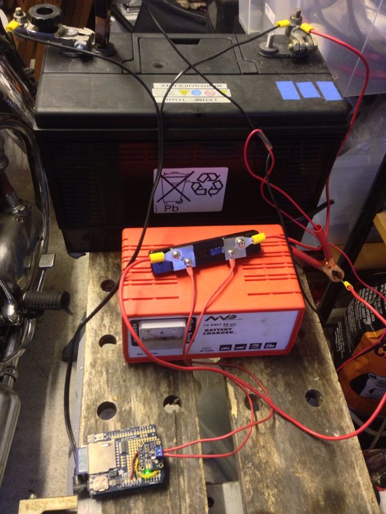
The Arduino battery monitor was set to record voltage, current and temperature every second to an SD card. The temperature was measured using a one-wire temperature probe that was taped to the negative terminal of one of the batteries.

Before I get on to the results.... let me just say, I can now understand why so many battery monitors out there give misleading readings, and why some of the papers I read on estimating battery capacity are so complex... the graph results are so complex. The end goal I'm aiming for here it to somehow reduce the mass of numbers I've accumulated into just one. A current battery capacity... e.g. 85%. Maybe even some kind of runtime until empty. But when you see they graphs you will realise why that is going to be so difficult.


Voltage and Current over Time
You will want to click on the image to enlarge it. It shows the raw voltage and current captured over the 3 days.

So I should probably talk through the top graph as to what exact was happening.

Thu 21:00: graph starts. Data is being captured, there is no solar charging as it is night time, and the compressor fridge is switched off. Nice smooth line with the voltage dropping slightly over time as surface charge from solar earlier that day drops off. Settles around 12.9V.

Fri 06:00: Sun comes up, voltage rises to a peak of 13.3V and current increases slightly due to charging from solar panel. We are on float charge.

Fri 08:00: I switch the compressor fridge on and load it with food for later, I also drive it from outside the house to the parking spot around the corner (so warden won't ticket me). You see a very brief spike in voltage as the engine charger kicks in taking the voltage up to 14.6V. The compressor fridge brings the voltage down and the graph starts to get 'messy'. The compressor on the fridge kicks in every 5 minutes and runs for a few minutes. This is what causes the min and max on both the voltage and current lines.

Fri 15:00 The sun comes out and the solar panel is now putting in as much as being taken out by the compressor fridge. You can see the highs of the current (red) line going above zero. The voltage is also going up to highs of 14.5V. The voltage oscillates a lot due to both the compressor fridge and also passing clouds.

Fri 18:00 I start the engine and we drive down to Weymouth. The drive is approx 2.5 hours. You can see the engine charge has kicked in and bringing the voltage max up to 14.7V. The current spikes up and down, but you can see a core downward trend on the current during the charging to finish at about 2A. As the battery is fairly well charged still and the solar panel kept up with the demand of the compressor fridge over the day, this is what I would expect. The engine charger doesn't need to put much charge into the batteries.

Fri 21:00 We are at the campsite and the sun has now pretty much gone down. The solar panel is not generating any power and the engine is off. You can see a baseline max current of 0A. ie, nothing. And a baseline minimum of around -4A. That is the compressor fridge drawing 4A of current from the batteries. You can see the voltage also drops down to a baseline max of around 12.8V and a min of around 12.6V. When the compressor fridge runs, the draw on the batteries causes the battery voltage to drop. You can see a slow downward trend overnight as energy is drawn from the batteries.

Sat 06:00 The sun starts to rise and you can see both the voltage and current increase.

Sat 10:00 A sudden drop for a while on both voltage and current. This is due to me unplugging the solar panel to see what the battery would settle to with no input.

Sat 11:00 The current rises following an arc as the sun moves across the sky. It was a pretty sunny day with no clouds. 

Sat 15:00 The solar panel has brought the voltage back up to a peak of 14.4v. So we could infer from this that the batteries have managed to reach full charge again (minus a 'topping off' charge or absorption phase').

Sat 17:00 Sudden drop in current and voltage. I've started up the Webasto diesel heater to heat some hot water for a shower. This heater has a pump that draws quite a bit of current, plus the glow plug for the heater which draws a lot to start with.

Sat 20:00 The sun is down, the van batteries are now losing their surface charge and again we start a night of the compressor fridge running and energy being drawn from the batteries. Once the surface charge is lost you see a slow downward trend on the voltage ending with a baseline max of around 12.7V. You see a number of very big downward current spikes to around -15A which I think may be that the reading was taken exactly as the compressor kicked in and that is the inrush current on the compressor motor.

Sun 06:00 The sun starts to rise again and the solar panel starts to bring the current and voltage up. We spent the day at the beach. It was a glorious sunny day. You can see the voltage and current rise and fall with the sun.

Sun 09:00 Short sharp dip as I fire up the heater to heat some water for a shower.

Sun 18:00 Another short dip as I fire up the heater again to make sure there is hot water to wash salt and sand of a very happy but tired 2 year old daughter who spend the day playing on the beach.

Sun 20:00 The sun is down, the surface charge is coming off the batteries and the current is alway negative as there is no charge source. Another night with just the compressor fridge drawing energy. The voltage drops to a baseline max of around 12.65V and a min of around 12.48V.

Mon 06:00 Sun is rising and current and voltage increase.

Mon 09:00 Heater on again for a bit for hot water to wash up.

Mon 14:00 We leave the campsite and start to drive home. You can see the engine charger kick in and take the current up to a peak of around 9A. Considering the charger can go up to 50A this seems a bit low, but I guess the batteries will determine how much current they will accept. The voltage is up to around 14.7V. The engine charger takes a break every 20 minutes to let the vehicle battery get some charge and to assess the charge situation. That is why there are voltage drops as we go along. You can see a steady downward trend on the current as the batteries charge and reduce how much they accept. This finishes at around 2A.

Mon 17:00 We are home. The van is parked up. For a while the compressor drieg keeps running until I get out to empty the fridge of things we didn't eat, and then switch it off. You see a small tail at the end of smooth line. The current is 0A and the voltage is around 13.12V.

So the big question is what does that all mean? How did the batteries hold up? How much charge did we take out of them? How long could we have stayed there before the batteries 'ran out'? Did the batteries get fully charged by the time we got home? So many questions! Well I'll answer them in the next blog post as I need to go get some real work done first!

Friday 24 May 2013

Out of Memory :(

I went out the the van last night and connected up the Arduino to the current shunt and battery and left it recording to the SD card. Alas, when I went out, the SD card had nothing on it.

After a long time messing about with it, and fearing I may have accidentally fried the SD Card, I worked out that the Arduino was out of memory. The Arduino One clone that I am using only has 2KB of SRAM to use. So all the variables that you define, strings you assign, etc. all have to fit in that 2KB. Which is really not a lot of room. Especially when you consider I don't actually have the State of Charge code written yet! So I'm out of memory and I haven't even calculated anything useful yet! I managed to pare it down enough for the Arduino to have enough memory to open the file on the SD card to write to it. Over this weekend I am going to go through and refactor my code some more.

I'm hoping this weekend, whilst we are away camping for the weekend, to try and capture a full 3 days worth of battery data. That is likely to be about the full runtime of my batteries, depending on the amount of sun and solar panel output. Once I get that data, I have a cunning plan. I'm going to try and write a simulator for the state of charge in Python on my laptop. I will be able to feed the raw data from the Arduino into it to run through a full 3 days in a number of milliseconds. This will allow me to tweak the algorithm and re-run it multiple times in order to try and get something that best matches the real world results as best I can. Alas this won't include any heavy charging from the engine, but should be a good start. The real goal for this is to have something that can keep track of my battery state over the space of a number of weeks involving multiple charge / discharge cycles and partial cycles.

New 'workshop'

Sorry I've not written much in a while. Truth is I've had hardly any time to work on the battery monitor. A few months back I managed to damage a trace on the Logshield board with my clumsy soldering and broke the 5v supply to the 3.3V regulator. That meant that the INA219 board (the voltage and current sensor) and the SD Card both had no power.

New magnifying glass and workbench
Since then we've managed to buy the house that we have been renting for the past 2 years (Yay!). As part of this I've been sorting out our garage and building better storage and a proper workbench in there. This now means I have a permanent place to work on the Arduino. I can now do soldering without worrying about melting the kitchen tablecloth! I also don't have to set up and tear down before every meal… so I can do some more ad-hoc work.

I also bought a cheap little magnifying glass off eBay. It is a great little unit with a weighted base, two croc clip claws on arms, a magnifying glass with LED lights and a soldering iron stand. Using this I was able to spot where I'd damaged the trace on the Logshield board. I was able to scrape away a bit of the protective top insulating layer on the board to expose the trace and solder down a strand of copper wire to repair it. It is not the prettiest repair, but hopefully should hold.

Last night I started putting everything back together again and put the Arduino in the van and connected it up to the 12v supply for power and to the shunt to measure current. The battery monitor now continuously transmits voltage, current and temperature readings via a MiRF chip. I have a second Arduino with another MiRF chip plugged into a laptop to read the readings and display them.

I'm pretty impressed with the range of the MiRF chips, with only an onboard PCB trace antenna I was still able to read the voltage from within my house, with the van parked outside. So that is going through the metal body of the van, and the wall of the house. And about 20 meters of air. As I'm only really wanting the RF transmission so that I can transmit data from the battery monitor to other Arduino units in the van (e.g. one with a 3G card so I can get data remotely, or to one in the van cab to display the readings) it has more than enough range.

The battery monitor is logging the values to the SD card on it, so I will be able to retrieve historical data, plot it, and try and work out a State of Charge (SoC) algorithm. The battery was fully charged when I left it for the dat today. I left the compressor fridge running, so I should get a day's worth of data as to how the current, voltage and state of charge relate. The sun is starting to come out and as I left the solar panel was putting in about 0.2A to the battery.

At the moment the current readings I've been seeing seem to vary quite a bit from what my Stecca solar regulator is reporting. I'm not sure which is accurate though. I did attempt to put my multimeter in series with the battery last night to see what it was reading, but for some reason it caused the load to cut in and out. I fear I may have shorted out my multimeter a while back and its current shunt is a bit damaged. If the current readings are out then it could point to the shunt not being the exact 15 milliohms that it reports to be. I don't have a meter accurate enough to be able to test that. I might see if the local Bristol Hackspace has a more accurate meter I can use.

This weekend we are away camping for the bank holiday weekend. We will be arriving on site on Friday evening and leaving Monday morning, so will have two and a half days running off the batteries so will see what data we can collect in that time.

Sunday 17 March 2013

New Bus Bars

I've been a bit quiet on here recently as I've been dealing with lots of non-van related stuff. One thing I've been meaning to do for a while is re-wire the electrics in my van to be a bit more robust. Originally all the cables came together onto a pair of M8 bolts (one for +12v and one for ground). But it was a pain to remove any cable, and I'm not sure the electrical connection was all that good.

So, I set about this weekend making up some nice heavy duty bus bars as part of my re-wiring project. These sort of things retail for about £50 each, and I certainly wasn't going to pay that!

I bought some stainless steel bar off ebay and cut it to length and drilled 7.5mm holes in it:

Posted Image

The holes were drilled with a battery powered handheld drill, so hence a bit wonky ;) And took quite a bit of time to drill through. A pillar drill here would have been ideal.

I bought a tap and die set and put an M8 thread in the holes. I bolted in some 25mm long M8 bolts. I also had a go at soldering the backs of the bolts to keep them in place and not turning when I do the nuts up on the front. This was a bit of an experiment as I know stainless steel can be difficult to solder unless you have the right flux. I used the normal flux and solder I use for copper pipe fittings and after heating it up with a blow torch I was able to get the solder to flow on pretty nicely. It needed quite a bit of cleaning up afterwards as the flux was all blackened.

I then glued the bars to some wooden blocks as standoffs. I should have left a bit more bar either end and then could have drilled a small hole in and screw it down, but I didn't leave enough room for this.

Finished bars:

Posted Image

And in place in the van:

Posted Image

I plan to put a dividing 'wall' between them and maybe a cover to reduce chance of shorting something across them accidentally.

I now have the shunt for the battery monitor permanently fitted in place, so can  now connect up the battery monitor. I'm still waiting for a FTDI cable from China to turn up so that I can program the Xino Basic board I have without having to resort to swapping chips around.

Saturday 16 February 2013

Simple, but it works

I have now removed the INA219 breakout board from my Arduino. It took quite a bit of work with the soldering iron to get it off. It is definitely toast. Putting 5v across it and it gets finger-burningly hot pretty quickly. So, I've ordered another one which should be here in a few days.

In the meantime I still wanted to try and get some more charge at 14.4V into my battery. As you may remember the last attempt to charge the battery stopped shortly into the constant 14.4v 'absorption' phase.

So I went old-skool and built a simple voltage divider using a 24K and 10K resistor on a breadboard. I calibrated in software against my digital voltmeter. I wrote a simple Arduino sketch to read the voltage from the analog input connected to the middle of the voltage divider and adjust a PWM pin connected to my MOSFET board accordingly.

I tuned the algorithm a bit to try and stop the oscillation I was seeing before:

void loop() {
  last_voltage = voltage;
  // read the input on analog pin 0:
  int sensorValue = analogRead(A0);
  // Convert the analog reading (which goes from 0 - 1023) to a voltage (0 - 5V):
  voltage = sensorValue * (5.0 / 1023.0) * ((25+10.0)/10.0) * 0.989;
  // print out the value you read:
  Serial.println(voltage);

  if (voltage > 14.4 && voltage >= last_voltage) {
    output_level -= 1;
    if (output_level < 0) {
      output_level = 0;
    }
  } else {
     output_level += 1;
     if (output_level > 255) {
      output_level = 255;
    } 
  }
  Serial.println(output_level);
  analogWrite(6, output_level);
  
  delay(500);
}

It seems to work and when the charger got to 14.40V it kept pretty close to that value and only oscillated by about 0.01V.

Arduino and breadboard with voltage divider on it to read voltage from battery

I am not able to log the current and voltage like before, so can't produce any graphs, but at least I can give the battery a good absorption charge. I can hear a bit of bubbling going on, so will check in a bit and may adjust the voltage down a bit if it gets too much.

Blown something up :(

Bollocks. Think I've somehow blown something up. After my last blog post I was going back to the garage to put the battery back on charge again. However when I tried to switch it on.... nothing. Taking the logging shield off the Arduino and the Arduino works again. So it is something up with the shield it looks like. My guess is the INA219 has somehow blown. Taking a reading from Vcc to GND on the shield I only get 6 Ohms resistance so seems that something has shorted somewhere. :(

Friday 15 February 2013

PWM charger works!

I soldered up the MOSFET circuit as per the last post and connected it up to my 'dumb' mains charger to charge one of my batteries overnight. You can just about see the MOSFET in the photo below sat on the bench with the wires coming in and out of it. The wires are red, but it is actually connected to the negative side of the battery.


I initially tried the MOSFET without the heat sink but it got finger-burningly hot. Attaching the heat sink meant you could touch it.

The Arduino was set to start the PWM pin at 0 and whilst the voltage was less than 14.4V increase the PWM output by 10, up to a max of 255 (100% duty cycle, ie. full on). If the voltage is greater than 14.4V reduces the PWM output by 10 to a min of 0 (0% duty cycle, ie full off).

Below is the graph of the current/voltage results:

PWM charging attempt, current and voltage
As you can see the charger only just got to 14.4V by the morning when I switched it off. But you can see it is holding the voltage around 14.4V. I'm not sure if the oscillation around the target voltage is due to my simple algorithm or due to the the fact the charger itself seems to pulse the current (as seen by the green band on the current in the graph). I could probably make my algorithm a bit smarted and get it to check the change in voltage between readings and not just the absolute values. This will probably allow it to converge on the right PWM value better.

My original intention was to hold the battery in absorption stage for a number of hours and watch what happens with the amount of current it accepts. It should get to a point where the change in the rate of current accepted flattens out. At that point I think that battery has taken all it can and the rest is just being converted to heat.

So I'll go out and switch it back on again so it can get some absorption charge. According to this page:


The Absorption time for my 110Ah battery being charged at 2A is 31 hours! That is way higher than I've seen elsewhere, but may explain why my batteries have not been getting enough charge in the past!

Thursday 14 February 2013

Building a Smarter Battery Charger

I currently have a very 'dumb' mains battery charger. As you may recall, this is the charger that took my battery up to 15.1v last time I tried it. I don't use this charger much, it was bought in an emergency to charge a start battery once upon a time. I've always believed I didn't need a mains charger as my Sterling B2B and solar panel should keep the batteries in my van in a good state. I've since worked out that it looks like they have been undercharging as whilst they have been OK to do a bulk charge, I never went on drives long enough to get to the 'absorption' stage of the charge.

So I've had an idea to build a PWM solar regulator to replace my Stecca PR3030. But I've realised I can use the same circuit to add some 'smarts' to my dumb mains charger. Mainly I need to to make sure that the voltage once it reaches 14.4v is held at that voltage for a few hours as the absorption stage, then drop down to a float charge. So, all I need to do is have something that can restrict the voltage that the mains charger is supplying to the batteries.

My plan is to use a logic level MOSFET to do this, controlled by a PWM pin on the battery monitor Arduino. In short, the Arduino will already be monitoring the battery voltage and so just needs to adjust the PWM rate, lowering it if the voltage goes above 14.4v and increasing it if the voltage falls below 14.4v.

I picked up some 'logic level' MOSFETs from RS today. This particular MOSFET can dissipate 167W and can go up to 40V or 106A. So should be fine to deal with the max 6A at 14.4v = 87W that my mains charger can put out. The idea of a logic-level MOSFET is that the gate pin can be driven directly by TTL voltages from the Arduino (ie. 5V). It is an N-channel MOSFET so will be connected to the negative lead and do 'low side' switching, as opposed to be connected to the positive lead. Connecting to the positive lead means you need more circuitry as the gate pin on the MOSFET has to be pulled higher than the source voltage (ie. higher than 14.4v).

This MOSFET also has a very low resistance between the source and drain pins. A quoted max 0.008 Ohms or 8 Milliohms. This means that at 6A I would get a voltage loss of 0.048V, which is insignificant for the mains charger. It is a bit of a waste for when I use it for solar panels, but seeing as the solar panels have an open voltage quite a bit higher (around 17-20V) then it should be OK. The regulator will be as close to the batteries as possible, so any voltage loss in the wiring from the solar panel to the regulator should happen before we drop the voltage down to 14.4V. This is one of the issues I think I have with my current solar regulator placement. It is halfway between the batteries and the panel and I think doesn't get an accurate reading of the battery voltage.

My plan is to solder the MOSFET to a small piece of stripboard with some screw terminals on the end. I plan to solder the wires along the tops of the copper tracks to provide some more current carrying ability. I also have a small heat sink to attach to the MOSFET to help with heat dissipation. The proposed circuit will be something like this:


The resistor across the pins of the MOSFET is a pull-down resistor, meaning it will keep the gate of the MOSFET closed if the Arduino is disconnected.

Sunday 10 February 2013

Adjusting fridge temp based on voltage

I stumbled across an interesting message board thread today:

http://www.fieldlines.com/index.php?topic=145714.0

Lots of good pictures and diagrams of someone's experiments with solar and building their own solar regulator.

One thing that particularly caught my attention was later on down the thread they start using a compressor fridge as a dump load for the experiments. They found the built in fridge thermostat drew a large quintessent load when the fridge was not running. They crated their own thermostat which monitored the battery levels and adjusted the temperature depending on what was available in the battery. This meant if they had 'excess' energy coming from the panel then they would chill the fridge to a lower temperature, and if less power available would run the fridge a bit warmer.

I have a compressor fridge in my van and have wondered about doing something along the same lines. My original plan was to have a temp sensor in the fridge and controlled by a microprocessor so that I could set the temperature to a known digital level. Currently you turn a knob inside to set the temperature and I never know exactly what it is set to. So I probably have it set too cold or too warm most of the time which is no doubt in-efficient.

Setting it so that it detect when we are driving and cools the fridge down to a lower temperature when there is excess power coming (from the engine) and maybe runs it slightly warmer at night when there is no power from the solar panel and we are likely to have less power in the battery bank. I could also maybe have different modes depending on what was in the fridge. ie. if I know we have meat int here then then I need to keep it to the correct temperature. If I just have drinks in there then it can afford to run a bit warmer.

The Danfoss compressor in my fridge also has a resistor in the controller in the back that controls how fast the compressor motor runs. I need to check what it is set to, but I think by default it is set to run the compressor as fast as possible. Whilst this means the fridge cools down quicker, it also means that the fridge draws maximum current and probably maximum in-efficiency. It also leads to uneven cooling in the fridge, with some areas frozen with others still warm. If I could control the fridge with a microprocessor then I could adjust the speed of the compressor depending on how the temperature changes. Ie. if the door opens and the temp increases rapidly then run the compressor fast to cool it down and then drop down to low speed to keep it at that temperature.

Saturday 9 February 2013

Calcium Technology

Doing some more research on what may have happened to my current batteries and how they are performing and I came across some interesting bits. The batteries I have are 'sealed' or termed 'maintenance free'. This is sold by the manufacturers as being a 'good thing'... but as we all know, there is no such thing as a free lunch. The issue here is that the batteries have to be charged much more gently than normal top-uppable batteries.

In order to prevent the excessive gassing that can happen with normal cells which can be topped up, maintenance free batteries have calcium in the plates. This helps prevent the gassing and helps the hydrogen given off to recombine to water inside the cells. The calcium also reduces the self-discharge rate of the battery.

It seems however there is an issue that can arise termed 'Antimony free effect' or 'passivation' which can affect batteries with calcium instead of antimony in the plates such as mine. Fulle details can be read in the comments of this page:

http://batteryuniversity.com/learn/article/charging_the_lead_acid_battery

But in short, a thin layer of lead oxide can form on the plates in the battery. Battery desulphators are not actually removing sulphation, but removing oxidation instead. So I'm hoping that the battery of mine with the desulphator connected might improve.

Doing some more reading, this page describes it in much more detail:

http://www.batteryvitamin.net/sulfation_pulse_treatment_surprise


We believe it to be highly significant that pulsing began gaining popularity in the early 1990s, only after all the major battery manufacturers had introduced low-maintenance and maintenance-free automobile batteries. These batteries have lead-calcium alloy grids. Lead-calcium batteries overwhelmingly fail due to something known in the trade as "passivation" or "open circuit". It has been described by battery technologists as the "antimony-free effect". 
Lead-calcium alloy develops an ultra-thin, very poorly conducting tetragonal lead oxide, (alpha-PbO), layer on the surfaces of the positive plate grids over time, leaving the positive active material in the positive plates isolated from the supporting positive grid structure. Battery manufacturers use tin to control this oxide layer. This is far from straightforward. Addition of more than 1.5% tin to the alloy reduces the passivation effect - critically, at 0.6%, tin actually provides a worsening of the effect. Tin is expensive, so as little as possible is used, with unpredictable results. There are more than 90 patents describing tin, as well as other metals, alloyed with, or plated onto positive grids - suggesting this too, is a highly problematic technology. Silver is even more beneficial but is excruciatingly expensive. Before lead-calcium, lead-antimony was the preferred alloy. Lead-antimony has always been absolutely 100% trouble-free in this regard.


There is also a long article on different charging regimes for sealed lead acid batteries:

http://www.intechopen.com/books/trends-in-telecommunications-technologies/traditional-float-charges-are-they-suited-to-stationary-antimony-free-lead-acid-batteries-

They suggest that the typical approach of holding a calcium/lead battery on float might cause excessive corrosion of the plates and cause premature failure ie. 3-4 year life rather than 20 year design life. They suggest that the battery voltage is allowed to fall and then is periodically given a small current charge at regular intervals to bring the voltage up.

There is also a report done by the US Navy on Calcium batteries used in submarines, which is also an interesting read:

http://torpedo.nrl.navy.mil/tu/ps/pdf/pdf_loader?dsn=5476298

They manufactured some identical cells half with lead-antimony and half with lead-calcium and put them through some charge cycles to see what happened. The lead-calcium ones ended up with very soft paste on the plates that very easily smeared off.

So it does seem that the addition of calcium to batteries versus antimony really is for convenience, but at a trade off of battery life.

Desulphator

It seems battery desulphators are a pretty contentious topic, and some swear by them, some say they are snake oil. I purchased a kit on from Courties Town Marine. I thought it was worth a punt to see if I could revive my dead batteries.

Kit of parts
I did manage to make a mistake on the very first component I soldered in. It was a large diode that I soldered in back to front. I realised as soon as i did it, and then spent about half an hour trying to unsolder it.

I seems that everything it working and that I haven't managed to damage the components with the excess heat.


I wired it up to the battery in the garage. This is the one that managed to charge up to 15.1v. It has been sat now for about 4 days and is still reporting 12.90v... which still seems quite high. I connected the desulphator up and the LED has come on and I can here the 1Hz buzz of it as it pulses the battery.


The MOSFET on it gets pretty warm. As in I can just about touch it briefly, but it doesn't melt skin warm. I think this is normal. My multimeter is unable to read the voltage whilst the dusulphator is connected. I'm guessing the, in effect, AC voltage is too much for it.

I'll keep an eye on it to make sure it is not overheating, but you need to run them for several weeks for them to work apparently.

-Matt

Monday 4 February 2013

Even further down the rabbit hole... An Arduino solar regulator

So, I'm accepting my batteries are dead. I will need new batteries. This brings about two questions:

  1. What batteries do I go for this time, and how many?
  2. What can I do to prevent these batteries from dying prematurely?
I've been umming and ahhing about going for 6v Trojan T-105 'golf cart' batteries for a a while now. In fact searching around, I actually found a thread I wrote when my last battery set died. I also found a great rant on batteries and solar panels that makes a lot of sense. See the last posts.

In the thread that I wrote on the SBMCC 2.5 years ago I also wondered about point 1 above:
Of course, then the question is.... what to replace them with  Another set of Exide Portapowers? Pretty cheap (£0.90/Ah), and lasted 3 years. Or step up a price bracket and go for Elecsol EL125's (£1.04/Ah) which are slightly higher capacity, but come with a 5-year warranty as opposed to the 2 year one of the Exides. 
Or even go a bit more exotic and go for Trojan T-105s (6v wired in series) would be £1.09/Ah. I think they might be a bit too tall for my battery space though, and as 6V, I'd have to go for 2 or 4 of them... and I kinda wanted around 330Ah.
So based on the last two posts, I think I'm going to go for a pair of 6v Trojan T-105 batteries. Wired in series they will give be 225Ah (C/20) at 12v. This smaller than my current bank of 345Ah, and my previous bank before that of 460Ah. But my plan is to get another one (or two) solar panels on the roof.

But this brings back an even bigger question about solar regulators.... can my current solar regulator charge at the higher 14.8v? Answer: No. It is a Stecca PR3030 and charges as 14.4v for flooded lead acid batteries.

I originally bought the controller as it had a nice State of Charge display on it with a bar graph and smiley faces. Yeah, I'm a sucker. It also has the ability to measure the current in/out of the batteries and keep a running total of Ah put in to the battery and Ah consumed. There are however two big drawbacks that I only discovered when I got in and started to install it many years (5? 6?) ago.

  1. The nice pretty State of Charge display can only work if solar is the only charging source. As I also charge from a Sterling B2B charger (from the van engine alternator) this mode can't work. So I have to put it in 'voltage' mode, which just gives a plain old voltmeter and no smiley faces :(
  2. In order to count the current going in/out, you have to wire all of you load negatives via the controller. This was a pain, and has resulted in un-necessary cabling and voltage drops. The van is metal bodied, and the body is grounded so in many cases I don't need a return wire back to the battery as I can ground the the chassis/body nearby.
So given all that, I'm not really getting much out of this controller. This battery monitor I'm building will give a much better reading and log of current going in/out of the battery bank and its voltage.

So... the next obvious question.... should I get a new/different solar charge controller?

....or actually.... can I BUILD one? ;) Given that all the controller has to to is take a voltage that may be significantly higher than the battery (17-19v) and drop it down to a suitable charging voltage (14.8v for bulk) and hold it there... couldn't I do this with an Arduino? How about the Arduino that I will already have connected to the battery bank doing the monitoring? Mwahahahahah! A cunning plan is forming and I'm heading yet even further down this rabbit hole of an experiment.

Luckily... as with much of the Arduino world (and why I love it do much) I can stand on the shoulders of others. A quick search around and I found someone already did something like this:


And yes, it is as simple as it looks. It just switches on the current from the solar panel to the battery (via a relay, or transistor) and switches it off again when the battery reaches the right voltage (e.g. 14.8v). Pretty simple.

EDIT: Or I might want to use something like a P-channel power MOSFET such as this with very low resistance across it. Someone has a great blog on using a MOSFET for a solar controller. Not quite as simple as I originally thought, but should be still easy enough.
EDIT 2: Or even better, use a shunt regulator system such as this.

This also has another benefit. One potential problem I have with my current setup is that the solar regulator is not that close to the batteries, it is up at head height and near the solar panel. This means there is potential voltage drop between the panel and the battery. Especially as the cable between the two also carries the load current as well. By putting the solar regulator next to the battery I minimise the voltage drop between the controller and the battery (or rather, I am able to sense the battery voltage at the terminals not several meters away at the current controller's location). It doesn't matter too much if there is some voltage drop from the panel itself as that is going to potentially be at a higher voltage anyway so can 'afford' to lose a few tenths of a volt.

A great rant on solar and batteries

I just came across this GREAT rant on solar and batteries. It is by a guy in the US who full-times in a big RV there. He makes a LOT of sense in his post. It is pretty long, but very much well worth a read:

https://handybobsolar.wordpress.com/the-rv-battery-charging-puzzle-2/

In short, he is advocating Trojan T-105 batteries. He is tending towards a smaller battery bank than you might think, but better charging regime. He is saying that T-105s could do with being charged at 14.8v rather then the generally accepted 14.4v used for most batteries. This actually gets a lot more out of a solar panel, as they generally run at a higher voltage anyway. Adding more batteries to a system (or more solar panels) without getting the charge voltage right and the wiring right is wasting a lot of power.

Deja Vu

In doing more research, I have managed to actually find a post from myself. In which I seem to have been asking the exact same questions before, and coming to the exact same conclusions. I guess you could ask, 'why haven't I learned?' I guess I have learned a bit, but clearly forgotten a lot as well in that time.

The posts were from the SBMCC (Self Build Motorcaravan Club) and dated the 7th August 2010. So around 2.5 years ago. I've copied and pasted them here, as you need to be a member to view them on the original site:


Hi all, I've got a question about battery charging and smart chargers... 
I've got 460Ah of battery on a 12v system (4 x 115Ah batteries) primarily charged with a 50A sterling B2B. So assuming I took it down no further than 50% it would take at very best scenario 4.5 hours to put 230A back into it assuming my alternator could put 50A in (no idea what it actualy puts in) and the charger gave it 50A continuously.
Now, I know smart chargers (mains or B2B) have several stages and start with constant current and then switch to constant voltage. According to Battery University the constant voltage stage is very necessary in order to make sure the batteries can hold the charge....
... so does that mean then unless I did a solid 4.5 hour drive (or I guess more like 10 hours, as its unlikely to get the optimum) I would never end up fully charging the batteries properly. 
Ie. if I did 5 drives each of 2 hours on different days, would it never do a full charge cycle? How do the chargers know how long to spend on each cycle? I presume they must monitor the resistance and voltage of the battery? So does that mean if the battery was very low it would take, say, 10 hours to do the full multi-stage process.... yet if the battery was only slightly discharged it would do the full cycle, but quicker?
The reason I'm asking all this, is whilst I have this massive battery bank, its has (especially recently) seemed to be much lower capacity than I would expect. I'm thinking this could be because the van only gets driven short hops, and hence the battery never gets a chance to have a complete full multi-stage charge and only gets the first stage of the charge repeatedly. Obviously age of the batteries is a factor (these are probably 3 years old now, but have been looked after fairly well). 
I've not got a mains charger installed in the van as we very very rarely ever stay on sites, so nothing to hook it up to. I have however just run the extension lead outside and plugged it my portable multi-stage 20A RAC charger to try and do a long full charge overnight to see what happens, as I've just uprated some of the cables in the wiring.
So seems I was already thinking that lots of small trips (ie small charing runs on the B2B) were conducive to good battery health:
I suspect what is happening is that I am doing lots of trip sin which the charger does stage 1 (constant current) but never gets to stage 2 (constant voltage) and hence it never gets to 'properly' charge the battery and so the battery always seems to be lower capacity even though I keep thinking I've put a fair bit of charge into it.
...and I seem to have been experiencing the same voltage drop symptoms as before:
Another data point. I've just gone out and checked the batteries. After taking the surface charge off by leaving around 3A of lights on for half an hour, each of the four batteries, measured individually is exactly 12.80V. 
However, when I put a 7.3A load on (halogen lights, compressor fridge, and 200W invertor running laptop)... admitedly an abnormally high load, the batteries read 12.54V at the battery terminals. They read 12.32V at the distribution point, so my cable upgrade has certainly helped with the voltage drop between the batteries and the distribution point. 
However, my question is.... is a drop from 12.80V -> 12.54V on the battery terminals 'normal' for drawing a 7.3A load from a 460Ah battery bank? When I switch the load off, the batteries return back to 12.80V (after about 5 minutes).  
So, hopefully now with building this battery monitor I won't be asking the same questions YET AGAIN in 3 years time ;)

Sunday 3 February 2013

Yeah, they are dead :(

So I think I'm coming to finally accept that my batteries really are not in a good state of health. I tested them today with a 4A load from a headlight bulb after giving them a hard charge last night. Here is the graph of the results. Ignore the current line, I forgot to connect the load after the shunt and so it wasn't recorded.

Testing the battery with a 12v headlight bulb (4A)

As you can see, the battery is sitting at quite a high voltage still... over 13 volts. When the load is added you can see the voltage drop dramatically. Even if the voltage had started at 12.8v the voltage drop down to 12.65v the first time (16:00) and 12.6v the second time (19:30), is not a good sign.

Voltage under 4A load
I stumbled across this bit taken directly from a Rolls battery manual:
Corrective equalization needs to be performed if symptoms arise such as a constantly running generator (low capacity) or the battery bank will “not hold a charge”. These symptoms are typical of a heavily sulfated battery. If a battery is not being fully charged on a regular basis or limited equalization is performed using a generator (see Bulletin 611, Generators, Inverters and Equalization) sulfation will occur from “deficit” cycling. This undercharge condition can take months before it becomes a major and noticeable problem. This under charge condition is caused when batteries are deficit cycled. The bank receives less of a charge each cycle and starts to sulfate. Eventually the sulfate will cause a resistance to charge and a “false high voltage” reading will occur. The “false high voltage” is measured by the charge controller, which further lowers the charging current to maintain the voltage set point. This further increases the undercharge condition. This is one reason why specific gravity measurements are so important as “false high voltage” readings can be misleading. See Bulletin 609, Voltage, SG and State of Charge for information on how to correctly interpret voltage readings.

I'm thinking this sounds like what has happened to my batteries. Thinking about it, my main charging source, the Sterling B2B only runs when my engine is running. I think I do many trips in which the full charging cycle will not have completed. This means that the batteries may not have reached the absorption stage of the charging routine. That combined with the B2B getting a bit confused by the solar panel keeping the voltage high means that the charging has not been idea. So as described above I think the batteries have a "false high voltage" and that has been fooling both the chargers and myself that the batteries are charged when they are not. So they are now badly sulphated and hence the high internal resistance.

If only I had a battery monitor that was able to log this information over time ;)

Well the next set of batteries is now going to have that device. That is what I'm building here. So the next set of batteries should last much longer. I'm also going to make sure I get normal flooded lead acid batteries that I can get the caps off to top up / test the electrolyte. I had that type last time and they worked well. This time I  didn't realise these batteries I have are sealed 'maintenance free' ones until after they arrived. They were a good price so decided to stick with them.

Now that solar panels have come down considerably in price I'm planning to buy an additional 80W panel to go with my 64W one. I will check the roof space on the van, might even get two 80W panels. That should mean that the solar regulator will be able to do a better job keeping the batteries charge up.

Overnight charging graph

Here is the graph of leaving the battery on charge overnight:

Voltage and Current on overnight charge
The charger I have is some bargain basement one I picked up from an auto store. My intention at the time was to find the stupidist heaviest cheapest charger I could find. My old Halfords automatic charger had died and I needed a quick replacement. I didn't want to spend money on something all singing and dancing as the plan was this charger was just going to be for occasional bench charging, or to feed 12v power into my Sterling B2B and use its 'cleverness' to feed the batteries.

I put the battery on charge with the Arduino plugged into it monitoring the current and voltage, as per the bench charge photo in the last blog entry.

This is not a 3 (or 4, or 7) stage charger. It just puts current into the batteries. So unlike the B2B when it kicks in, it doesn't immediately raise the voltage up to 14.4v. As you can see it is putting in around between 1 and 4 amps to start with and seems to pulse the current as seen by the solid green band. Watching the current readings so by on the serial terminal it looked like it did a few seconds of 3-4A then dropped to 1A for a second then back up again. You can see the voltage slowly raises and the current reduces as the voltage increases. I left it going overnight expecting to have reached around 14.4v or so by the morning. Slightly alarmingly it had brought the voltage right the way up to 15.1v. This is considerably higher than you should take a lead acid battery as they start to gas, usual at around 14.4v... but the addition of Calcium in the battery can raise the gassing level. My batteries are 'maintenance free' which is actually a stupid term which just means 'once the electrolyte has boiled off, you can't top it up'. But some batteries do do some cleverness to catch the gas and try and re-condense it back into the battery. My batteries have no obvious vents in them, so I can't see anywhere for the gas to escape. They didn't seem warm or bulging or anything so I hope not damaged them.

In effect what I have done is what is termed an 'equalisation charge' which is when you the battery up to a higher than normal voltage to try and get all 6 cells in the battery to the same level. This invariably causes some gassing in the battery and does overall reduce its lifetime, but on the other hand lessens (supposedly) the chance of one cell lagging behind the others and eventually dying prematurely rendering the battery useless (which actually happened to one of my previous batteries).

Many places say you shouldn't try and equalise a sealed battery as it causes gassing, which is bad. That makes sense. But I'm hoping doing this as a one-off has had a positive effect. I'm kind of working on the basis that if I can't revive these batteries and get their performance up to where they should be then I'm going to be needing to buy some new batteries anyway. So kill or cure.

When I checked the battery this morning and it was at 15.1v I could hear some sound from the battery, so I'm guessing it was gassing. If there was some sulphation on the plates, then hopefully this will have helped to remove some of it. time will tell.

I switched the charger off and left the battery to see what the voltage would return to. As you see in the graph, shortly after 8am, when the current is stopped the voltage dramatically drops to around 13.5v and then slowly drops of thereafter. At the end of the graph it is at 13.22v and you can see it is slowly falling still. There is no load on the battery other than the Arduino itself, which is pretty small, but hopefully enough to put enough load on the battery so that we get meaningful voltage readings.

I might try and find  aspare headlight bulb to wire up to the battery to see what that does to the voltage reading. Fingers crossed, if I've managed to revive this battery then we should see a much smaller voltage drop when the load is applied (after taking into account the surface change still on there holding it above 12.8v).

Saturday 2 February 2013

Bench Charge

I've taken one of the batteries out of the van to bench charge it to see if I can nurse it back to better health. Here is a quick photo of it in the garage connected to a charger via the Arduino and shunt. The Arduino is recording the battery voltage and current to the SD card.

Battery on bench charge with battery monitor

Another graph

Went out for a drive today. Here is a graph of voltage and current over time. I've tried to scale it so that 0 Amps is at the same position as 12.8V on the y-axes.

Current and Voltage over time whilst driving
The interesting thing is that the Sterling B2B is only putting in 16A of charge when driving. The charger is rated to 50A and the alternator is 75A, so I should be able to get some more current in. Indeed, when I switched on some load the battery with the charger running, the battery was still getting a constant 16A, which means the charger has current to spare, but the battery can't take it.

I think I would expect a battery to be able to take more than 16A charge rate. The general recommended rate for charging a lead acid battery is 20% of its Ah rating. ie. for a 115Ah battery, it should ideally be charged at 23A. So I would expect the battery to be able to take more.

I did notice that my Sterling B2B charger has been on the 'Gel' setting all the time I've had these batteries (2.5 years). The charger actually has a 'Sealed Lead Acid' setting, which is more appropriate. According to the manual the Gel setting has a slightly higher float voltage, but the main difference is it's bulk stage duration says '12-24 hours' versus '1-12 hours' for the SLA setting.

So I'm now wondering if my batteries have been being undercharged all this time. Thinking about the general pattern of charge on my batteries they are either charged by the Sterling B2B when driving or by the solar panel when stationary. I've long suspected that the Sterling gets confused by the solar panel. When we start driving, the Sterling B2B charger measures the voltage on the battery bank and from there works out how long the bulk charge stage should be. Since the solar panel is always on, the batteries read a higher voltage then they really are. So I think the Sterling has been running the bulk cycle too short. This combined with being on the Gel setting maybe means they have never reached the end of the bulk stage properly.

Voltage/Current reading overnight

I left the arduino logging current and voltage readings to the SD card last night. I switched on the fridge in the van and a pair of halogen lights. It looks like the fridge attempted to run right at the start but then gave up. I'm guessing as it was running from just a single battery, the low voltage cutout kicked in straight away. This is not a good sign for the health of my batteries :(

Voltage and Current readings of single 115Ah battery overnight
As you can see, the voltage drops down immediately as a load is applied. It was sitting at 12.80 volts at rest. As soon at the load of 3.5A was applied the voltage dropped down to around 12.45v and then kept falling overnight. What is interesting is the shape of the voltage line over time. With a constant current it takes a distinct change in slope at around 1 hour in.

When I went outside to switch the load off at 7:30am you see the current immediately drop to near zero and the voltage immediately jumps up. It then takes about an hour to stabilise. Then settles at around 12.3V.

I'm not sure exactly what this is telling me, apart from something does not look right. The total Ah discharged over the 9 hours is 29Ah. Which is about 25% of the capacity of a 115Ah battery. The battery was at around 10 degrees C last night, so would have had a bit smaller apparent capacity than the stated 115Ah. That said the 115Ah is the C/20 rate (ie. when drawing 5.75A) so we were drawing less and so that probably would have cancelled out the effect of the cold.

A voltage reading of 12.3V indicates a state of charge of approx 60%. I'd be expecting, based on the Ah drawn to be around 75% SoC at the end, and so a voltage of approx 12.40V.

I'm about to take my daughter out to pay for the weekend, and will leave the monitor connected to the battery and hopefully we will see the effect of the Sterling B2B charger kicking in.

Friday 1 February 2013

Shunt Arrived!

My 50A shunt has finally arrived from China! So I went out this evening to connect up the shunt to the batteries and the Arduino.

Arduino battery monitor connected up to shunt and batteries
Oddly, I couldn't get the current reading calibration right. There is a calibrate method in the INA219 library, and I passed in the various values for the shunt and voltage and the readings kept coming out too low. I connected my multimeter in ammeter mode in series with the shunt and found I was 2.3 times too low. So I've multiplied up in the code and putting various loads on the batteries it seems to keep in tally with the multimeter, so I've left it like that for now. Voltage readings were much better now than my last attempt.

The black wire you can just about see in the photo is powering the arduino via the barrel socket and voltage regulator. It is connected directly to the battery terminals. The voltage reading was still a bit low is is multiplied up in code by 1.0034 and now it tallies with my multimeter for the range of voltages we are interested in. Of course my voltmeter could be inaccurate anyway, but these readings now do feel right, and also tally with what the Stecca solar regulator thinks the voltage is (although that only has one decimal place, the change from 12.7 to 12.8 for example seems to happen the same on the Stecca and the Arduino now).

There are 3 batteries in the bank, but I've disconnected two of them via the quick-disconnects I have on the negative terminals, so I'm just measuring one individual battery.

Interestingly I appear to have a small 0.05A parasitic load on the batteries from somewhere. I'm guessing it might be the Sterling B2B or the Webasto Thermotop in sleep mode. Everything else goes via my main control switch panel and is switched off. And no, it is not the Arduino itself, I've already discounted that from the figure ;)

So I have left it logging again overnight. I've left two halogen spots on (about 3.5A in total) and the fridge on (about 3A on 50% duty cycle). So this should discharge a single battery a reasonable amount. I should be able to go out tomorrow morning and switch the loads off... will leave it some time to stabilise and then pull the SD card out and we can look at the results now we have current and more accurate voltage readings.

I probably should have disconnected the solar panel too... as that will probably start charging when the sun comes out in the morning.... well will be interested to see if we can see its effect on the graph. It is meant to be a sunny day tomorrow.

Thursday 31 January 2013

First Graph

I now have the first graph of the battery onitor output as captured to the SD card!
Plot of voltage over time

The graph is a plot of the voltage of my battery bank from just after midnight until just before 8am in the morning.

Two important facts:

  1. My battery bank appears to be dying. The internal resistance of the batteries seems much higher than it should be. This means a load on the battery drops the voltage more than it should
  2. The voltage measurements are not accurate. According to my digital multimeter the tops of those peaks should be closer to 12.8v. So I think we are reading approx 0.1v too low. I believe this is due to a voltage drop over the earth connection in my test setup.
I had the compressor fridge on throughout the night and the cyclic nature of the plot is the fridge compressor kicking in. It was about 15 degrees C in the van and the fridge was kept closed and was fairly empty.
I had the Webasto diesel heater on at the start of the plot so you can it brought the voltage down low as the glow plug was on. I ran the heater twice more: around 1:45am for about half an hour, and again at around 7:20am for about half an hour.

Zoom in of one section
Zooming in you can see that when the fridge kicks in the voltage drop is around 0.24V which if the fridge is drawing around 3A equates to an internal resistance on the battery of around 80 milliohms. Which whilst better than previous measurements still seems pretty high.

The time is missing from the X-axis, but the fridge is kicking in about every 5 minutes.


Wednesday 30 January 2013

Damn... dead batteries :(

This evening I've been out in the van playing around with the battery monitor as it stands. I still don't have my shunt yet, so can't connect it up to read current. However it should still be able to read voltage (via the INA219).

Initial results are a bit disappointing.  The readings I was getting from the INA219 were wildly different from the readings I was getting from my digital voltmeter. Now, my digital voltmeter is only a cheap one from Maplins, so it could be inaccurate too, but its readings do correspond to what my Stecca PR3030 solar regulator int he van say. So on that basis I think the battery monitor is the one reading wrong :(

It would seem that the way I had connected it up to test it (via a cigarette lighter socket in the van, supplying a nominal 12v to the Arduino) didn't work to well. The reason being the ground connection. It would appear that there was a 0.3v potential difference between the ground on the Arduino and the ground of the battery terminals. This means that the ground path from the lighter socket back to the battery (via a convoluted route, including the Stecca PR3030) is not all that good. When I connected a wire directly the readings seemed a bit better, but were still quite a way off. I'm hoping that when I connect it up properly via the shunt and with a direct connection to the battery negative terminals that I will get a more accurate reading.

But the bigger... and worse news... its seems that my batteries are dead :( I switched on a light in the van drawing 1.4A from the battery as measured by putting my digital voltmeter between the battery terminal and the wire normally from it. The voltage drop as recorded by the DVM was from 12.80 - 12.63 volts. ie. 0.17v. Using Ohms law that means 0.17V / 1.4A = 0.121 Ohms. Or 121 milliohms. This is the internal resistance of the battery, and should normally be in the range of 5 - 10 milliohms. 121 milliohms is very high and indicates that there is a problem with the batteries. All three batteries of mine exhibited similar behaviour. [Thanks to eagle eyed Stewie for the correction that at 1am this morning I wrote amps instead of ohms for the resistance figures above]

The batteries are coming up to 3 years old, and have been used quite a bit, but I am pretty careful with them and they never get left in a discharged state, so I am a bit disappointed that they have died already. I was hoping to get at least another year or two out of them. So I'm going to do a bit more investigation, but seems like these batteries might have had it :(

Tuesday 29 January 2013

Idea for SoC algorithm

I'm still waiting for the 50A shunt to turn up from China, so can't connect the battery monitor so far to test it out. My plans are to remove a single 115Ah battery from my van (of the three) and bring it indoors and connect it up in a stable, warm environment for initial tests. I should be able to then connect up the shunt, and wire up a spare cigarette lighter socket I have lying around and plug my small 150W inverter into it. I can then plug a desk lamp into the inverter. This should give me a nice stable load of a few amps.

I can then run the battery down, with the monitor connected and logging to SD card, and see how the voltage varies with the load. It will also give me a chance to try and estimate the number of amp-hours the battery can hold. My batteries are coming up to 3 years old this summer, so it will be interesting to see how they are still performing.

Last night I started coding some of the Arduino software to deal with estimating the state of charge of the batteries.

There are two types of battery monitor, the ones that just look at voltage, and the ones that count the charge going in/out of the battery. I'm hoping to do a hybrid approach of both. You can only really get a good estimate of the SoC by looking at the voltage if the battery has been 'at rest' for some time. This gives you an absolute reading of the SoC. Counting the charge in and out can be done at any time, but only gives you a relative SoC reading and is prone to drift. You also need to calculate things like charging factor (e.g. it can take 1.2-1.3A charging input to store 1A of charge). And deal with Peukerts law (drawing a large current is less efficient than a small current).

The problem with voltage readings is that a battery in a motorhome is seldom 'at rest' due to continuous loads such as the fridge compressor kicking in and lighting etc. However my battery bank is designed to let us run for 3-4 days off-grid and there *are* times when the batteries are at rest (e.g. at night when lights are off and fridge comes on less often as isn't opened as much, and cooler ambient temperature).

So my cunning plan is to try and periodically take 'at rest' readings when the battery *is* at rest. And the estimate between those readings by counting the charge going in and out. Hopefully when the next 'true' reading is taken it can be compared against the estimate so far by counting the current and the parameters used for counting the current can be updated to provide more accurate estimates.

We should be able to then extrapolate these readings to calculate the effective capacity of the battery bank. As this will be based on actual voltage readings, it should effectively compensate automatically for battery age and temperature.

 I decided to work on a state system in which the batteries can be in one of four states: UNKNOWN, ATREST, CHARGING, LOAD. When it starts up the batteries are in UNKNOWN state, and then progress though the other states as things happen. ATREST is defined as when the load on the batteries is between 0.1A and -0.1A.

When the state changes, I store the time of the state change and the last state in some variables. I then check if we are in the ATREST state and how long since the last state change. If the last state was CHARGING then we must be ATREST for at least an hour before we take a voltage reading. If the last state was LOAD then we must have been ATREST for 5 minutes. These timings are just a guess, but from what I've observed of the batteries before they seem to 'settle' much quicker after a load then after charging. I think this is due to 'surface charge' on the batteries.

Once I have a 'true' voltage reading after being at rest, I then calculate the SoC as:
soc = 100 - ((12.80 - voltage) * 100)
Again, we can tweak this once I get a better idea, but seems about right, with 100% SoC being 12.80v and 50% SoC being at 12.3v.

When I take a 'true' reading I will zero a variable the counts the charge that has gone through the system. Every second when I take a current and voltage reading this counter will be updated with the Ah that has been removed/added to the battery and will be used to estimate the SoC since the last 'true' reading. When the next true reading happens I can then compare it to my estimated SoC and adjust variables accordingly.

Wednesday 23 January 2013

Initial Success!

The Data Logging Shield with INA219 breakout soldered on,
on top of an Arduino Uno
So, the Data Logger shield by Adafruit turned up today. This is their new version which is full assembled, so very little work to do. All you have to do is solder on the header pins (plain or stacking depending on what you want to do).

This shield has a real time clock, SD card reader and a small prototyping area. So ideal for what I want. I soldered the header pins on then attached it to my Arduino Uno. I uploaded a number of test sketches from the Adafruit website to test it and within minutes had both the RTC and the SD card slot working. I have a donated SD card, but had left it in the office today as wasn't expecting the data logger shield to turn up so soon. So, being impatient I pulled out the SD card from my camera to use that. I wasn't expecting it to work, as the cards need to be formatted, and apparently the SD card reader sometimes have trouble with cheap cards.

But lo and behold, the test sketch was able to open the SD card and print out a directory listing of the files on the card... being a camera card this took quite some time!

So now I knew the shield was working, I set about soldering on the INA219 breakout board (also from Adafruit) to the card. This is the current monitor that I'm testing out which read both the current (across a shunt) and the voltage and reports them back over the I2C bus. The I2C bus is already in use on this card for the RTC, but you can have multiple devices on the bus as they all have separate addresses.

I soldered the breakout board to the shield, and then soldered up the 4 necessary wires: +5v, ground, SDA and SDC. The shield has a couple of nice holes to connect SDA and SDC up. It took me a few goes to get the hang of soldering up wires on the prototype area. So far I've only ever used stripboard, and not had to create my own bridging connections before. I worked out the best way (after some trial and error) was to run the wires on the front of the board and push them through to the back through an adjacent hole to what I wanted to connect to. I then pushed the bare wire over and soldered it to the adjacent pin.

I then set about writing a sketch to see if I could get everything working together. Taking examples from all the various components (INA219, RTC, SD card) I was able to put it all together. The only piece I'm missing at the moment is a temperature sensor. I want to get some pcb screw terminals to solder to the board so I can then fit in a Dallas Semi 1-wire temp sensor to the board. I've seen some nice assemblies on eBay that are the 1-wire temp sensor enclosed in a small metal tube, sealed waterproof and on the end of 1 meter of cable. These would  be idea, as ultimately I'd like to have the temperature sensor physically connected to the battery, probably to the negative post on the battery. I should get enough conduction to get a decent reading of the battery itself. I could probably crimp the temp sensor into a ring terminal as a way to mechanically attach it to the battery posts.

Values recorded from the battery monitor stored on the SD card
Anyway.... it all works! I am now talking a time, voltage, and current reading once per second and writing it to the SD card. I'm flushing the SD card every 10 seconds. After a while I pulled the SD card out and connected it to my laptop (via my camera) and opened up the file in OpenOffice... tada! So I just need to work out a way to get OpenOffice Calc to recognise a unix timestamp and I can then graph the results. At the moment it is not connected to a shunt and the INA219 has not been calibrated, so is showing odd readings. Hopefully the 50A shunt I ordered from eBay should turn up soon and I can fit this to the van and test it out.

The next stage is going to be to have some way to set a nominal battery capacity in Ah and start keeping track of the current going in and out and having a first stab at trying to get a state of charge estimation. This is where it is going to start getting all fun with Peukerts law, and related things!

Monday 21 January 2013

SD cards and 3.3v

So it seems that whilst the SD card reader I ordered from China *says* that it will work with 5v or 3.3v it doesn't actually have the necessary circuitry to drop the 5v signals down to 3.3v. This means that there is a very good chance it will damage any SD card put in it if run from 5v.

I have a couple of options:
  1. Ignore it and hope 5v won't blow my SD card up
  2. Build some level shifting circuitry to drop the 5v signals down to 3.3v
  3. Buy an existing Arduino shield with a SD card reader and that circuity built in.
No, I can can make my own (option 2) and there are instructions online from someone else on how to do this. But to be honest that kind of sounds like too much work. Well, I'm not afraid of work per se, but there is an expression in the IT world called Yak Shaving and this is apt here.

Actually, Adafruit make a quite nice Datalogger Shield which contains both a SD card reader (and level shifter) and also a Realtime Clock. It also has a prototyping area on there on which I could put the voltage/current sensors and the temperature sensor.

This would increase the cost of the project a little bit (maybe about £10) but would mean a lot more of the system is pre-assembled and would make it much easier for others to replicate.

This actually means I could get all of my circuitry I need for this project on a single shield, which could then be put on top of any Arduino (ie. an official 'full fat' Arduino or a bare-bones one such as the Xino Basic that I plan to use.

Sunday 20 January 2013

Measuring Voltage and Current

The main thing this system needs to do is measure the voltage of the batteries and the current going to and from them. This may sound simple, but isn't necessary so. As it is the main function of this device it deserves its own blog post.

At the moment I have two different approaches to measure the current that I am investigating:

There are pro's and cons to each approach, so I've got one of each sensor and will have a play with each of them to see how they go.

ACS714 Hall Effect Sensor

This sensor is good in that is is isolated from the current wire and there is no electrical connection between the sensor and the system being sensed. The sensors however can only measure up to 30A each way. My Sterling B2B charger can put in 50A which would overload this sensor. The sensor would not be damaged, but would just read a maximum of 30A. I have 3 batteries in parallel and so I could attach 3 separate sensors, one to each battery. This means a total of 50/3A or 16A would go through each sensor to each battery. I can then sum the current in software. This has the advantage that I could detect if there are any abnormalities in the batteries, such as a failed cell, that would cause one battery to take a higher/lower current than the others.

One of the main disadvantages of this sensor is that the current itself has to flow through the sensor. This means running a wire from the positive terminal of the battery to the sensor and then from the sensor to my main power distribution point and fusebox. The sensor seems pretty small and I'm not sure how it will like having 16A pushed through it for long periods of time.

The sensor outputs an analog voltage between 0 and 5v that corresponds to a current reading of -30A to +30A. The Arduino has 6 analog inputs that have a 10-bit analog to digital convertor (ADC) . This means it reports values of 0 to 1024. Whilst this will give us a current reading, I would still need a way to get a voltage reading. This is normally done using a pair of resistors to divide the voltage to an appropriate value to be read. In our case, by using, say a 10K Ohm and a 20K Ohm resistor we can scale a voltage of 0 - 15V to 0 - 5V to be read by the Arduino. This does however require us to get very accurate resistors. Another issue is that the Arduino's ADC relies on having an accurate 5v feed in order to accurate measure inputs. If the 5V feed fluctuates or is not exactly 5.00V then the readings from the ADC will be inaccurate.

INA219 High Side DC Current Sensor

This sensor is designed to read the very small voltage drop that occurs over a resistor when a current passes through it. This is the approach the Nasa BM-1 takes and any other system you see that requires a 'shunt' to be fitted. The advantage of this system is that it can be scaled to measure any current by using different resistance shunts. So I could measure 50A in/out of the whole battery bank by using a suitably sized shunt. The accuracy would depend on the accuracy of the shunt, but you can calibrate the sensor based on the resistance of the shunt, so I can measure the shunt resistance once it is installed and adjust accordingly.

This sensor communicates with the Arduino via I2C which is a digital protocol, rather than an analog signal. This means that we are not reliant on the Arduino's ADC to provide accurate readings. Multiple sensors can be attached to the same I2C bus should I want to take separate readings from each battery as above. This sensor also measures the voltage as well, which means we don't need to bother with a voltage divider as detailed above. A library has been created to read the INA219 sensor from an Arduino, which makes it very easy to interface with.

The INA219 is a very very small chip and way beyond my soldering skills to try and solder it directly. Luckily Adafruit have created a INA219 breakout board for it which makes it much easier to work with. The disadvantage with this board is that it has a 0.1 Ohm resistor already attached to it to measure the current. This means that it is only able to measure up to 3.2A. You can however un-solder the 0.1 Ohm resistor and run wires to an external shunt. So I have a 50A shunt on order, again from China via eBay. Once it arrives we will see how it works with the INA219.